

JET BOAT ENGINE COOLING TECH 12/04
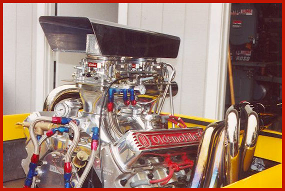
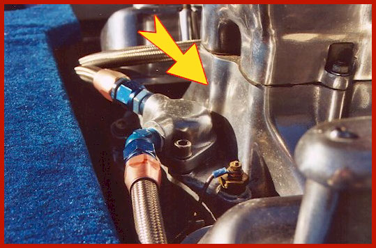
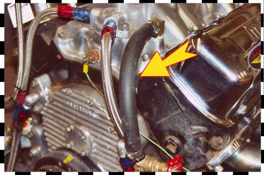
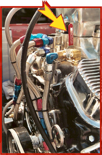
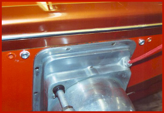
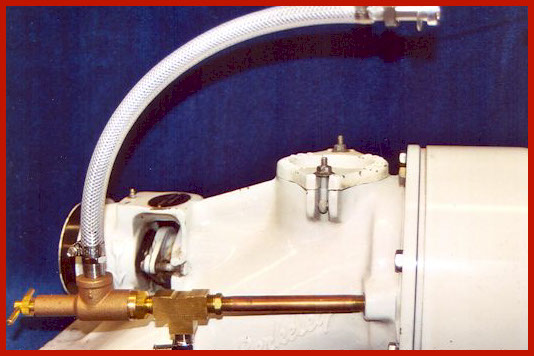
Bypass thermostat and header feed. Note manifold pressure relief valve. I used this set up in early
experiments with pressure relief. This set up works good, but it is cheaper to run a new water
source for the headers and add a second dump line off the thermostat housing.
Over the years there has been a lot of discussion and misunderstanding with regard to the best method of keeping your jet boat engine plumbed and cooled properly. In this article I will try to explain the problems and solutions to this frequently asked question in the simplest manner possible.
With jet boats, there exists a number of problems with the factory cooling system design that have come to light over the years. First, most jet boat engines run too cool for optimum performance. Secondly, some set ups are prone to excessive water pressure problems in the engine block as high pressure is taken from the jet drive and routed into the engine cooling system. Third, jet boats with water injected headers tend to have the problem of using too much water which ends up contaminating the oil in the crank case. To address these problems you need to understand how most jet boats were plumbed from the factory and how these factory set ups were supposed to work.
I will start with the standard jet boat set up with a through transom exhaust system utilizing log exhaust manifolds and risers. In these systems water is pumped from the jet drive through a gate valve to a tee fitting under the front of the engine. The water is split and directed to the front of the engine where the water is pumped into the exhaust logs on each side. Once in the exhaust logs, water is preheated and routed to the front of the block where the water pump would normally be located. Water runs through the block, on each side, up into the heads and exits out the engine through two fittings on the thermostat housing. From here, the water is carried to the risers and dumped overboard out the exhaust. This set up works pretty well except for the fact that the cold water runs through the engine so quickly that the engine temperature usually runs too cold. In a performance engine, I like to see a temperature range of 140 to 180 degrees. You may disagree but I feel that all jet boat engines are performance engines.
To deal with this cold water temperature issue, the factory folks installed a gate valve close to where the water exits the jet (for cooling). The idea was to gate down the water flow to the engine until a desirable temperature was reached and leave the valve set at that position.
The problem with this set up is that by closing the coolant valve, you reduce the amount of water flow to the engine and if you go a little bit too far, you end up with a condition where the engine block is running at a good temperature but the cylinder heads run too hot due to the lack of enough water volume. A lean condition can result in your engine, causing blown head gaskets, cracked heads, tuliped valves, or worse, a blown engine. This problem is especially acute with the 455 Oldsmobile engine. The improper adjustment may also cause extreme swings in engine water temperature from idle (very hot) to wide open throttle (very cold), which is not a good thing. The solution to this system is to use a bypass thermostat kit on the engine to regulate engine temperature. Leave the water valve full open or remove it altogether.
There are two thermostat kits on the market and PERFORMANCE JET sells both of these items. The cheaper of the two is made of aluminum and will fit the big Chevy and Olds engines, on most manifolds. A more expensive unit is made by Hardin Marine and is made of stainless steel. This unit is supposed to fit the Chevy, Olds, and Ford big block. It works well on the Chevy and Olds but does not fit well on most Ford applications without cutting or modifying the base of the unit. There is a better way to go on the Ford engine application, as I will explain later.
Once the engine temperature issue has been addressed, the next step is to deal with the possibility of high coolant pressures in the block. If you are running a blue printed jet drive in the higher RPM ranges at higher speeds, with a lot of power, then you are likely to have excessive pressure in the block. The average jet drive can build pressures in excess of 150psi and the engine cooling system is designed for no more than a maximum of 22-25psi. Excessive water jacket pressures can cause head gasket and intake manifold gasket problems and water in the oil. Once again, Oldsmobiles are especially vulnerable to this problem. Mondello likes to see 12-14psi in the cooling system of the Olds engine. Over the years there has been a lot of heated debate on how to deal with this issue of high coolant pressure, but to me, the solution is really very simple. You must dump at least as much water out of the engine as you put into it. If you still have too much pressure then install a pressure relief system that reduces the pressure before water enters the engine. In the first system example I just discussed, there are two water inlets and two water outlets. Excessive water pressure is usually not an issue with these stock set ups. Water temperature and volume are usually the two primary problems that I see with the stock exhaust log/riser combo.
In most cases I see, the issue of high water pressure in the engine block really becomes a problem when the jet boat is set up with water injected headers. On these systems the water comes from the jet to the front of the motor, splits at the tee and enters the block where the water pump would normally be. So far so good. The problem arises with the factory design to get the water back out of the engine.
In most factory set ups, one water line exits the thermostat housing and feeds the header tee valve. The other water line on the thermostat housing routs to the transom of the boat, through a gate valve, then dumps overboard through a transom dump fitting. The gate valve is supposed to help adjust water pressure to the headers. Closing the valve forces more water to the header tee because it can't dump overboard. Opening the dump valve reduces the flow of water to the headers by dumping more water overboard. This set up does not work well in reality. The problem is that this set up puts far too much water to the header tee valve and excessive water in the headers puts water in the oil. Secondly, there is only one full size line that is dumping water from the engine and it is not enough to keep the engine block water pressure from climbing. Problems usually start when there is too much water reaching the headers. To control excessive header water the jet boater will install a header water control valve somewhere in front of the header tee. When the water is reduced to the headers so they don't milk up the oil, you are cutting down even further the amount of water that can get out of the engine and the engine block pressure goes up even more as a result. Throw in the fact that half of the jet boaters out there don't have a clue as to how the system is supposed to work and you have a recipe for real problems. I've seen a lot of customers turn valves, just to turn valves and they really don't know why. Turns out that a lot of these people are just guessing.
The solution to high water pressure in the engine block is still simple, but you have to change some of the factory plumbing. First, you take the water line that feeds the headers off of the thermostat housing and put it aside for a minute. You add a new dump line (5/8"ID) hose and put it on the fitting on the thermostat housing that fed the headers. Run this line back to the transom and connect it to a new dump fitting. So, you should now have two dumps coming off the thermostat housing and going overboard at the transom. On the original dump line that had the gate valve, get rid of the valve and put it aside. Use 5/8"ID hose. Note* Always use 5/8"ID hose or -10 hose when you plumb the water system on your engine, don't go smaller. I also like to use 3/4"ID hose or -12 hose from the jet drive to the water tee at the front of the engine, especially if you run an oil cooler. The header feed line can be smaller, 1/2"ID or -08 is good. Now we have two inlets and two dumps on the system. The engine block pressures should be greatly reduced.
You now need to find a water supply source for the headers. No problem. On your intake manifold water crossover (under the thermostat housing) you should have a pipe plug, or two, that block off water in the manifold water jacket. Take one of these plugs out and install a 90 degree hose fitting and connect your header line to this fitting. Take that gate valve that you put aside from the original dump line and install it between the 90 degree fitting and the header tee. Now you have water control to your header tee without restricting the amount of water exiting your engine. Really, you can take water from any other source to feed your headers. Legend and Aggressor jet drives have two water fittings on their jets and you can even use one of these to feed your headers. If you are using the electronic water control valve, you will need a cold water source for the headers. You could even tee off of the water supply line somewhere before the engine inlet to feed your headers.
Note* Headers do not need a lot of water. Just crack the valve open very slightly so that you have a fine mist or steam exiting the headers off of idle. Header water should shut off completely below 1500RPM if the header control tee is working properly. With very large cams the water should shut down to the headers at 2000RPM. The factory header tee valve just does not do the job in this case and the electric water control system is best. PERFORMANCE JET Sells the Banderlog header control valve for this application.
Add a bypass thermostat to this set up and you have solved the problem of engine temperature, coolant pressure and proper header function. In some high output applications you may still have too much coolant pressure in the block. If this is your situation, then install a pressure relief valve system on your jet drive water feed in addition to what I have just discussed in the set up above. PERFORMANCE JET sells our own pressure relief kit for $149. I set them to open at 12PSI so that extra pressure is dumped overboard before it reaches the engine. (and you still maintain full volume.) They work great.
Now, for you Ford guys, good news. A four-part thermostat kit has been developed for the Ford 460. Just bolt one of these kits on, and your cooling issues are solved. This kit is sold in this site's cooling link and sells for $169.
In my opinion, these are the basic solutions for most engine cooling problems for the average jet boat. PERFORMANCE JET can set you up with everything that you need, or you do it yourself, but remember, don't skimp. Buy good parts and do the job right the first time. Remember your jet boat is supposed to be a pleasure boat. So keep it that way.